STP

In this post, we will have a look at the venerable Spanning Tree Protocol (STP), what it is used for, and how to configure and verify it on Cisco IOS and MikroTik.
STP Theory
STP (802.1D) prevents switching loops. Without it, a LAN with redundant links is susceptible to:
- Broadcast storms, resulting in
- MAC table instability; and
- Multiple frame transmission
A broadcast storm is caused by a broadcast frame that is put on a LAN that has a loop. It never dies, because it is flooded out every interface of a switch, except the interface it came in on.
Because the same broadcast frame comes in on different ports of a switch with the same source address, the switch keeps updating its MAC table: the entry is flapping.
Another consequence of a broadcast storm is that the same frame will be delivered multiple times to the destination, and it might just be that the application cannot handle that correctly.
STP makes sure there is only path from a switch to a so-called root bridge. The root bridge gets elected among all available switches in the broadcast domain.
Root Bridge Election
The election works as follows: using a so-called Hello configuration Bridge Data Protocol Units (BPDUs), each switch advertises itself as the root bridge to its neighbors. It does this by including a root and sender Bridge ID (BID) that consists of a 2-byte priority field and a 6-byte system identifier:
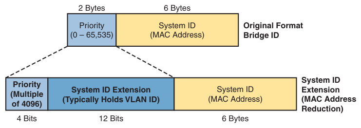
A lower priority value indicates higher priority. The system identifier is equal to the switch’s burned-in MAC address.
The Hello BPDU includes the following fields:
| Field | Description |
|---|---|
| Root BID | BID of switch the sender of this Hello BPDU believes to be the root bridge |
| Sender’s BID | BID of switch sending this Hello BPDU |
| Sender’s root cost | Root path cost between the sending switch and the current root |
| Root’s timer values | Hello timer, MaxAge timer, forward delay timer |
A neighbor receives this BPDU and looks at the advertised root BID. If the root BID is superior (meaning the priority is higher than what it currently thinks of as the root), it will:
- change the sender BID in the Hello BPDU to its own BID
- change the sender’s root cost to the cost between this switch and the root; and
- forward the modified Hello BPDU out its other ports.
If the priority is lower (inferior), however, it will just ignore the BPDU.
By default, the 2-byte priority field in the BID is equal to 32,768 (or 0x8000
in hex). In that case, the system ID (the burned-in MAC address) is used as a
tie breaker: the lower the 48-bit MAC address value, the higher its priority
(1111.1111.1111 wins from 2222.2222.2222).
After a while, the root will be elected and the network will start to converge (= stabilize on a network topology).
STP Roles and States
After the election, each switch’s interface takes on a role. These roles can be:
- Root Port (RP): the single port on a switch facing the root switch that
has the least cost path to the root switch. Root ports are chosen by:
- root path cost
- BID of the upstream device
- bridge port ID of the upstream device (consisting of a port priority and a
unique ID, such as
128.1)
- Designated Port (DP): a port (facing away from the root switch) on a segment that has the least cost path to the root switch. This port will forward the Hello BPDU onto the segment.
Because the elected root switch has the lowest cost path (0) to the root on all its ports, all of its ports will be designated ports (DPs).
The cost of a path to the root is determined by looking at the current speed (not maximum speed!) of the links that lie between a non-root switch’s port and the root switch’s port. By default, traversing a 100 Mbps link carries a cost of 19, while a 1000 Mbps costs 4:
| Ethernet Speed | IEEE Cost 1998 (short) | IEEE Cost 2004 (long) |
|---|---|---|
| 10 Mpbs | 100 | 2,000,000 |
| 100 Mpbs | 19 | 200,000 |
| 1,000 Mpbs/1 Gbps | 4 | 20,000 |
| 10,000 Mpbs/10 Gbps | 2 | 2,000 |
| 100,000 Mpbs/100 Gbps | N/A | 200 |
| 1,000 Gbps/1 Tbps | N/A | 20 |
On IOS, you can switch between the 2 short and long methods by:
Switch# spanning-tree pathcost method <short|long>
Set the interface cost for an interface:
Switch(config-if)# spanning-tree vlan 1 cost 123
Note that on IOS, you set the cost per VLAN on an interface. That is because IOS uses a modified version of STP called the Per-VLAN Spanning Tree Protocol (PVST+)1, which is a topic for a separate blog post.
With STP, every interface can be in state:
- Blocking (stable)
- Listening (transient)
- Learning (transient)
- Forwarding (stable)
- Disabled (stable)
(Between parentheses whether the state is a stable state or an intermediate state towards a stable state.)
Root Ports and Designated Ports will be forwarding frames. If a port is not a RP or a DP, it will be blocked. That means that it will not receive nor transmit user frames. It will still receive BPDUs, though.
If an interface is administratively shut down, its state will be “disabled”.
On IOS, you can check on all of this with show spanning-tree:
Switch#sh spanning-tree
VLAN0001
  Spanning tree enabled protocol rstp
  Root ID    Priority    24577
             Address     000B.BE6A.4623
             Cost        19
             Port        1(FastEthernet0/1)
             Hello Time  2 sec  Max Age 20 sec  Forward Delay 15 sec

  Bridge ID  Priority    28673  (priority 28672 sys-id-ext 1)
             Address     00D0.BA39.4B87
             Hello Time  2 sec  Max Age 20 sec  Forward Delay 15 sec
             Aging Time  20

Interface        Role Sts Cost      Prio.Nbr Type
---------------- ---- --- --------- -------- ---------------------------
Fa0/2            Desg FWD 19        128.2    P2p
Fa0/1            Root FWD 19        128.1    P2p
Timers
A root bridge sends a Hello BPDU every 2 seconds by default. This Hello Time is carried in the BPDU. It also contains a value for MaxAge, which defines how long switches should wait after ceasing to hear Hellos before trying to change the STP topology. By default, it is 10 times the Hello Time. So a switch will wait 20 seconds for Hellos to come in before taking action.
The forward delay timer is used to determine how long a switch will stay in listening and learning states after deciding to transition a port from blocking to listening.
In the listening state, the switch processes BPDUs but does not forward any user frames. It tries to determine whether the interface should indeed be forwarding or should return to the blocking state. It makes this decision based on the received BPDUs. Also, the switch removes unused MAC table entries for which no frames are received during this period.2 In the learning state, the switch begins to learn the MAC addresses of frames received on the interface.
All in all, a switch could take 50 seconds (20 MaxAge, 2 times the forward delay for listening and learning) before an interface transitions from blocking to forwarding.
Edge Devices
Only switches participate in STP. Edge devices (PCs, laptops, IoT, etc.) do not.
But the links that connect edge devices to switches will, by default, still go
through the motions by first entering listening state and then learning state.
You can short-circuit this process by configuring spanning-tree portfast on
the interface. The link will now transition to forwarding immediately.
In the event you do connect a switch to a port that was configured with
portfast, you can inadvertently create a loop. In that case, you should also
enable BPDU Guard on the port by setting spanning-tree bpduguard enable. If
the port detects a BPDU coming in, it will automatically disable itself.
MikroTik
On MikroTik’s RouterOS 7, make sure you have STP enabled:
[user@rb] /interface/bridge/set BR1 protocol-mode=rstp
(Even though this post is about the traditional IEEE 802.1D STP, please enable the more modern (faster!) RSTP instead.)
Check the status of a bridge:
[u@rb] /interface/bridge/monitor BR1
                  state: enabled
    current-mac-address: 48:A9:8A:11:11:11
            root-bridge: yes
         root-bridge-id: 0x8000.48:A9:8A:11:11:11
         root-path-cost: 0
              root-port: none
             port-count: 23
  designated-port-count: 5
           fast-forward: no
It indicates this bridge is the root bridge (current-mac-address == root-bridge-id) and has a BID of 0x8000.48:A9:8A:11:11:11: here, 0x8000 is
the priority in hex (= 32,768 in decimal; change with set BR1 priority=0xNNNN
to a multiple of 4,096) and the system ID is the 48:A9:8A:11:11:11.
Check an individual port:
[u@rb] /interface/bridge/port> monitor [find interface=ether17]
            interface: ether17
               status: in-bridge
          port-number: 16
                 role: designated-port
            edge-port: yes
  edge-port-discovery: yes
  point-to-point-port: yes
         external-fdb: no
         sending-rstp: yes
             learning: yes
           forwarding: yes
     actual-path-cost: 10
     hw-offload-group: switch1
It automatically discovered that interface ether17 is connected to an edge
device. If you want to be specific, you can set PortFast by set [find interface=ether17] edge=yes. Set BPDU Guard with set [find interface=ether1] bpdu-guard=yes.
Change between the long and short automatic costs based on interfaces speeds:
[user@rb] /interface/bridge/set BR1 port-cost-mode=long
And a bit of warning: RouterOS does not currently play well with Cisco’s PVST. It will treat it as regular multicast traffic.
-
The
+at the end indicates that IEEE 802.1Q is used for trunking instead of Cisco’s older, proprietary ISL protocol. ↩︎ -
This state was subject to dispute, as it is unclear whether it matters if STP is learning MAC addresses or not here. It is telling that RSTP has done away with this state. ↩︎