IEEE RSTP and Cisco RPVST+ Interop
Let’s have a look at what happens when we plug some MikroTik devices into a Cisco switch and string them together in a loop topology. What happens when RSTP and RPVST+ need to work together? Do we get a broadcast storm? Why (not)?
Interaction of RSTP with RPVST+
RSTP is VLAN-agnostic. The 12-bit System ID Extension in the BID is set to all
zeroes 0000.0000.0000. Cisco’s proprietary (R)PVST+, on the other hand,
populates this field with the ID of the VLAN on which the BPDU containing the
BID is broadcast.1

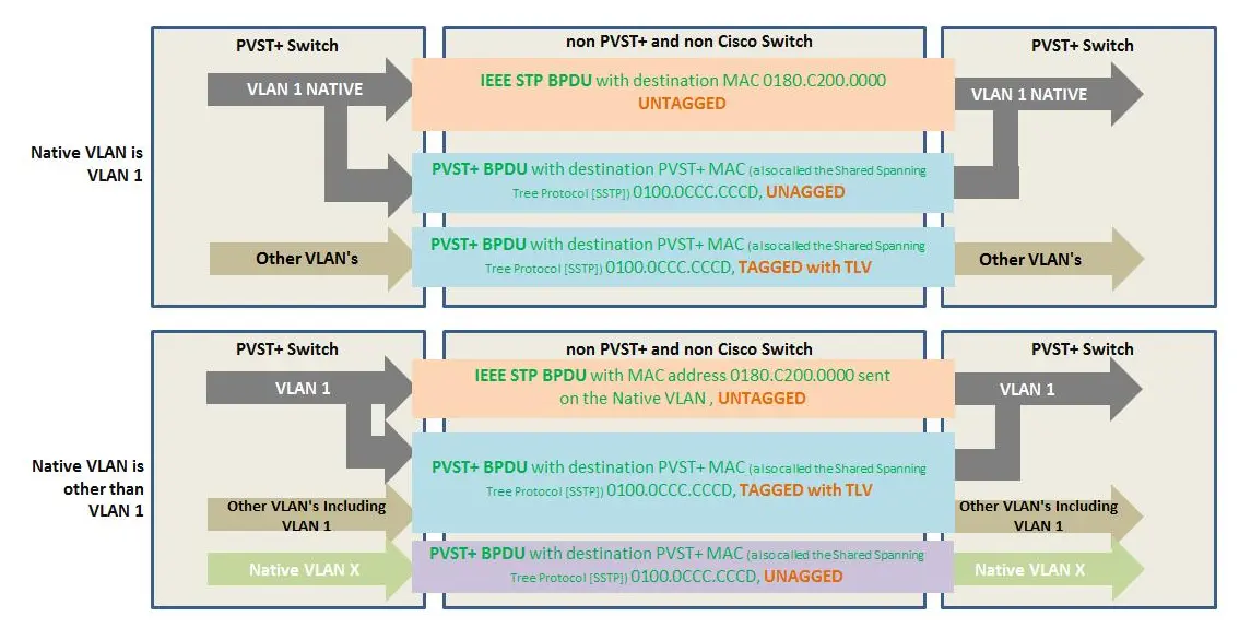
RSTP sends untagged multicasts to 0180.C200.0000 onto the native VLAN,
creating a single Common Spanning Tree (CST). Cisco’s RPVST+ sends tagged
multicast frames to 0100.0CCC.CCCD on every VLAN, creating a separate tree for
every VLAN. So, if you have 10 VLANs defined, RPVST+ will send 10 BPDU Hellos
every Hello interval.
This also means that Cisco and MikroTik gear do not play (well) together. MikroTik treats Cisco’s proprietary (R)PVST+ frames as it would any other multicast and forwards it out all ports except the port it received the frames on. Cisco will discard multicast traffic sent to the IEEE multicast address if VLAN 1 is not the native VLAN and not allowed on the trunk.
I found the following image on the Cisco Community: it helps explain the
situation when the native VLAN is the default 1 and when it is something else:
This is the topology we will use to think about different scenario’s:
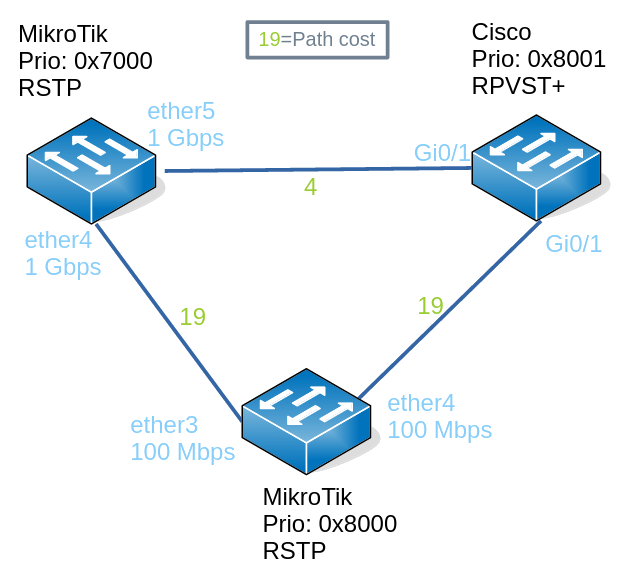
I won’t repeat the interface names (ether5) in the scenario topologies,
because for MikroTiks, they are pretty much meaningless. Plus the maximum speeds
of the interfaces can be deduced from looking at the path cost. All paths costs
are in the traditional IEEE 1998 form (see this post) where 100 Mbps links
have a path cost of 19 and 1 Gbps links a cost of 4.
The MikroTiks, a hEX and hAP lite, run 7.19.1 firmware. The Cisco, a 3650C, runs a venerable 15.0(2)SE2.
Scenario 1: Everybody Uses Native VLAN 1
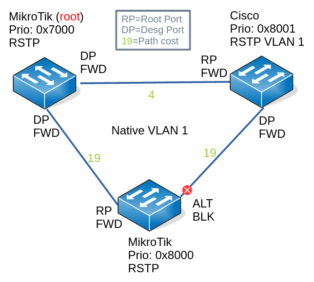
In this scenario:
- VLAN 1 is the native VLAN
- VLAN 20 is tagged
What happens in VLAN 1:
- Cisco sends untagged VLAN 1 BPDU both to IEEE and Cisco addresses
- Cisco processes untagged RSTP BPDUs coming from MikroTiks under VLAN 1
- STP converges and blocks a port to prevent a switching loop
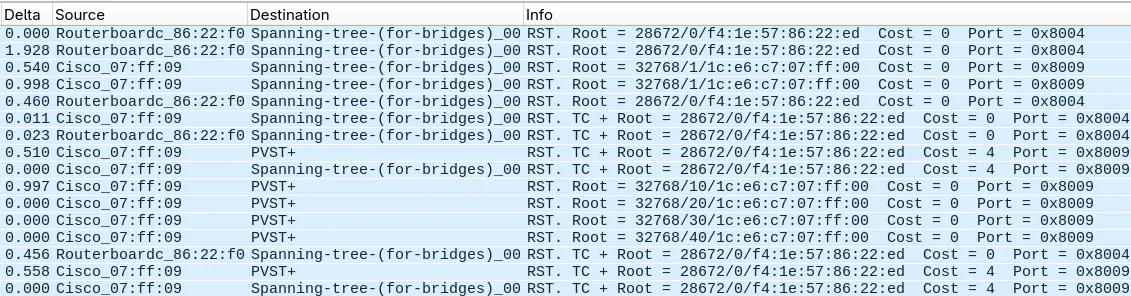
What happens in VLAN 20:
- Cisco starts out assuming it is the root bridge on VLAN 20
- Cisco sends tagged VLAN 20 BPDUs2 to the Cisco address
- MikroTiks see Cisco address as just another multicast address and flood it
- For a brief period of time, before VLAN 1 STP converges and blocks a port, Cisco receives its own BPDU on its other interface and decides that it’s connected to a shared segment
- Cisco transitions the port with the lowest port priority to the backup role and discards incoming traffic on that port
- After VLAN 1 converges and a port is blocked, Cisco stops receiving its own BPDUs on the backup port, decides that a topology change has taken place and transitions the port’s role from backup to designated port
In the (R)PVST+ world, the Cisco switch will be the root on all VLANs because there are no other contenders: the switch will never hear anything from anybody, because the MikroTik at the bottom has blocked its outgoing interface to the Cisco switch.
Switch#show spanning-tree vlan 20
VLAN0020
  Spanning tree enabled protocol rstp
  Root ID    Priority    32778
             Address     1ce6.c707.ff00
             This bridge is the root
             Hello Time   2 sec  Max Age 20 sec  Forward Delay 15 sec

  Bridge ID  Priority    32788  (priority 32768 sys-id-ext 20)
             Address     1ce6.c707.ff00
             Hello Time   2 sec  Max Age 20 sec  Forward Delay 15 sec
             Aging Time  300 sec

Interface           Role Sts Cost      Prio.Nbr Type
------------------- ---- --- --------- -------- --------------------------------
Gi0/1               Desg FWD 4         128.9    P2p
Gi0/2               Back BLK 19        128.10   P2p
Interface           Role Sts Cost      Prio.Nbr Type
------------------- ---- --- --------- -------- --------------------------------
Gi0/1               Desg FWD 4         128.9    P2p
Gi0/2               Desg FWD 19        128.10   P2p
Any loops?
- After convergence in VLAN 1, a port is blocked and no loop is possible
- This blocked port also prevents loops on RPVST+ VLAN 20, even though the Cisco put both its ports in forwarding state
Scenario 2: Native VLAN 20, VLAN 1 Allowed on Cisco Trunk
Things get more interesting when you change the native VLAN.
In this scenario:
- VLAN 20 is the native untagged VLAN
- VLAN 1 is just another VLAN allowed on the trunk
With regard to VLAN 1:
- Cisco sends untagged VLAN 1 BPDUs to the IEEE address
- Cisco sends tagged VLAN 1 BPDUs to the Cisco address
- MikroTiks process untagged VLAN 1 BPDUs as RSTP messages
- MikroTiks flood tagged VLAN 1 BPDUs just like any other multicast traffic
- The network converges and the same port is blocked as in scenario 1
With regard to VLAN 20:
- Cisco sends untagged VLAN 20 BPDUs to the Cisco address
- MikroTiks flood tagged VLAN 1 BPDUs just like any other multicast traffic
- Because a port gets blocked by RSTP on the MikroTiks, the Cisco port with the lowest priority first becomes a backup port and soon afterwards a designated port, just as in scenario 1
Again, loops are prevented: a flooded broadcast, unknown unicast or multicast (BUM) frame arriving on the MikroTiks will not result in a broadcast storm. Also, any BUM traffic arriving on the Cisco switch from any of the other VLANs via access links will also not cause a broadcast storm because the MikroTik blocks all traffic on all VLANs.
Scenario 3: Native VLAN 20, VLAN 1 Disallowed on Cisco Trunk
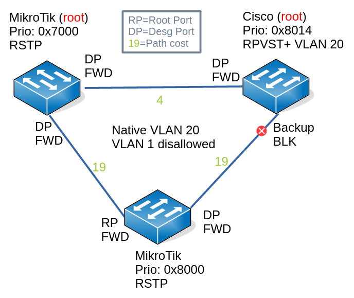
In this scenario:
- VLAN 20 is the native untagged VLAN
- VLAN 1 is not allowed
With regard to VLAN 1:
- Cisco does not initiate any BPDUs to the IEEE address
- Cisco drops received BPDUs addressed to the IEEE address
- MikroTiks see that Cisco does not participate in the root-bridge election by initiating its own BPDUs or forwarding them, so the MikroTiks ports facing the Cisco switch automatically become the designated ports
With regard to VLAN 20:
- Cisco sends untagged VLAN 20 BPDUs to the Cisco address
- MikroTiks flood untagged VLAN 20 BPDUs just like any other multicast traffic
- Cisco sets a port with the lowest priority to be the backup port and discards traffic
A switching loop is prevented, because all traffic (both tagged and untagged) coming in on the Cisco switch will not be switched out of the (discarding) backup port.
In the image above, note that it merges 2 views. Cisco views the world as the root bridge of the native VLAN 20 with no other contenders. Because it receives its own RPVST+ BPDU on its other port, it designates the other port as a backup and blocks traffic over it. The MikroTiks have another view of the native VLAN (might be or not VLAN 20): because the Cisco does not initiate or forward IEEE RSTP BPDUs, it considers ports going out to the Cisco to be designated ports and forward traffic over them. So we end up with 2 isolated root bridges. But all is well and no loops occur.
Conclusion
So is it safe to mix MikroTiks and Cisco bridges with regard to switching loops? The answer seems to be yes, at least for the simple 3-bridge topology and different configurations I examined here. As to more complex topologies and configuration, we can say a couple of things:
- Cisco’s proprietary (R)PVST+ BPDUs will always be flooded by MikroTik bridges
- Those MikroTik bridges build their own CST, making sure there is no loop between them, blocking ports where necessary
- If the Cisco bridges do not forward the IEEE RSTP BPDUs (when they do not allow VLAN 1), the MikroTik bridges will forward on those interfaces.
- That would be problematic, were it not that the Cisco switches consider those ports to be connected to a shared segment (a hub, basically), transition them to backup roles and start discarding traffic.
It’s another question entirely whether all of this results in the most efficient traffic flows. If analysis shows it isn’t, it would be best to consider the IEEE’s standardized Multiple STP on both the MikroTiks and Cisco’s. But that’s a topic for another time.
