Quality of Service (QoS)
Let’s have a look at QoS or how to unfairly manage traffic in the face of congestion on Cisco devices.1
What Is QoS and Why Do We Need It?
QoS is concerned with 4 characteristics of network traffic:
- bandwidth (capacity of a link)
- delay (between sending a packet and the recipient receiving it, or RTT)
- variation in delay (jitter)
- packet loss
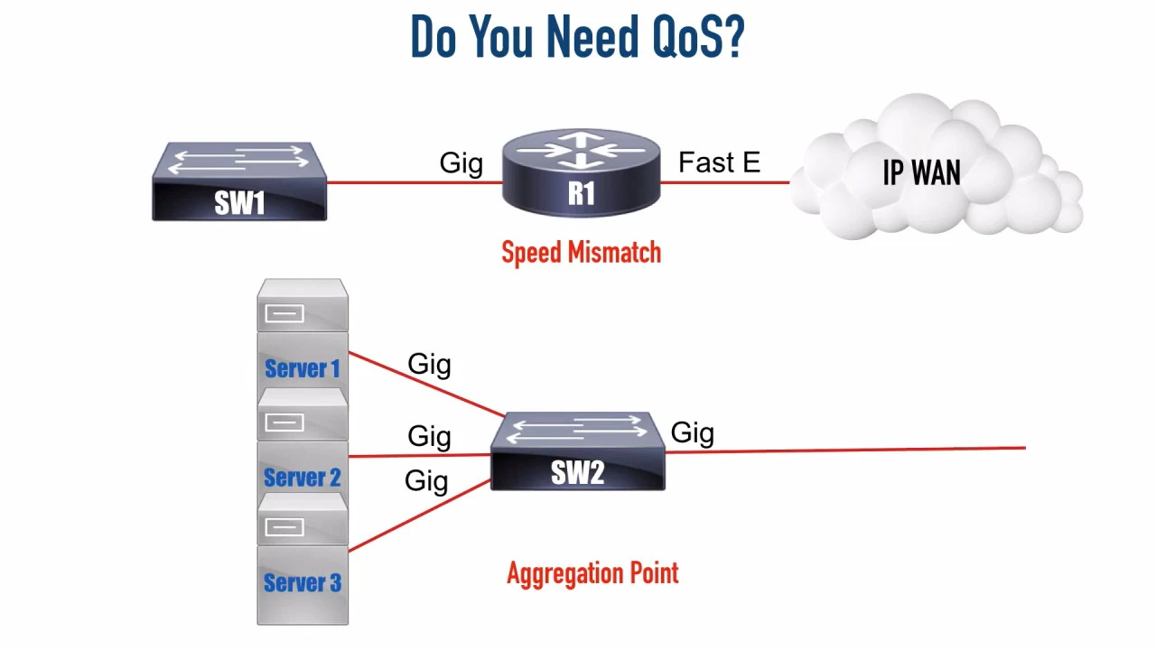
QoS comes into play when the network is not able to process every packet as soon as it received, which is most always. Think of a gigabit data stream coming in on 1 interface and having to leave a 100 Mbps link on the other end (speed mismatch). Or several gigabit links on a switch receiving traffic at capacity all having to use the single gigabit uplink to the ROAS (aggregation point).
QoS is good for when we have periodic congestion. If we are congested all the time, we simple need more bandwidth.
Some types of traffic (voice, interactive video) are much more sensitive to timing (delay, jitter) and loss than others (web browsing). If we do not have any QoS, then all the traffic gets the default, best-effort treatment. This comes down to FIFO, where the first packet that arrives is the first packet that is scheduled to leave the outgoing interface. Heavy downloading can delay or even drown out voice traffic, resulting in a poor Quality of Experience (QoE) for the end user on a VoIP call.
We have 4 tools to change the QoS characteristics of certain flows in the network:
- classification and marking
- prioritization through queueing
- policing (dropping2) and shaping (delaying through queuing)
- congestion avoidance (random drops or ECN)
Classification and Marking
Cisco recommends to classify and mark traffic as close to the source as possible. Marking traffic on access devices prevents having to classify traffic over and over again on distribution or core devices (which are really meant to do bulk forwarding, not classification). We might also not be willing to trust marking from end devices, but overwrite any received markings in trusted access devices under control by IT (the trust boundary lies in the access switch).
Classification can happen at the datalink layer or the network layer.
Datalink/Layer-2 Marking

Inside an IEEE 802.1q trunking frame, there are 3 bits that can be used to set a Class of Service value: priority bits (also known as Priority Code Point [PCP]). In theory, we could set 8 different priority values. But Cisco says we are not allowed to use the highest 2 values, value 6 and 7, because they are reserved for network use. So, effectively, we can set any value from 0 through 5, with 0 being the default (no priority).
Even if we are not using trunking on an interface, we might still be able to use IEEE 802.1p. That is the same as 802.1q except that the VLAN ID (VID, the last 12 bits of the 4 bytes) is set to all zeroes.
The IEEE has made some broad recommendations on how to set and interpret these CoS values:
| PCP value | Priority | Acronym | Traffic types |
|---|---|---|---|
| 1 | 0 (lowest) | BK | Background |
| 0 | 1 (default) | BE | Best effort |
| 2 | 2 | EE | Excellent effort |
| 3 | 3 | CA | Critical applications |
| 4 | 4 | VI | Video, < 100 ms latency and jitter |
| 5 | 5 | VO | Voice, < 10 ms latency and jitter |
| 6 | 6 | IC | Internetwork control |
| 7 | 7 (highest) | NC | Network control |
Network-Layer/Layer-3 Marking
The problem with layer-2 CoS is that the markings do not cross router boundaries. We need something similar in IP and we have it in both IPv4 and IPv6.
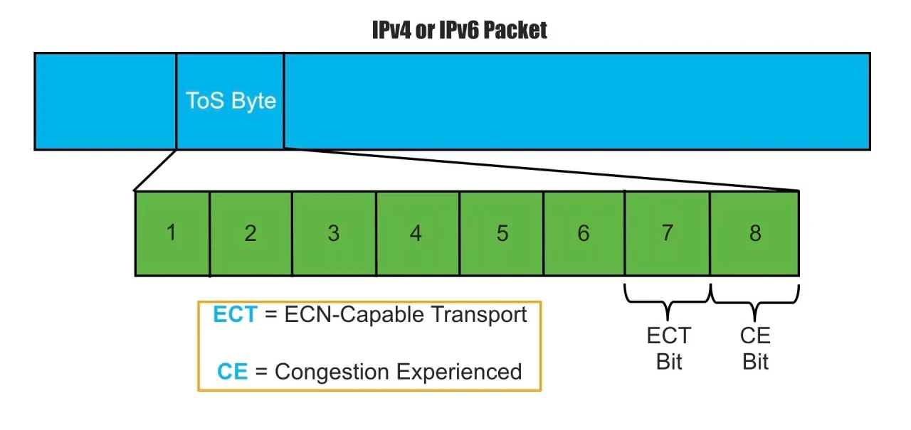
The 2nd byte of the IPv4 header is called the Type of Service (ToS) or Differentiated Services. The 2nd and 3rd nibble of the IPv6 header is called “Traffic class”. The function is the same: the first 6 bits are used to indicate the Differentiated Services Code Point (DSCP) and the last 2 bits are used for Explicit Congestion Notification (ECN).


Differentiated Services Code Points
Before DSCP was around, the first 3 bits of the ToS field were interpreted to be the IP Precedence (IPP). These looked a lot like layer-2 CoS. Here, too, 3 bits means 23 = 8 different priority values and, again, Cisco would not allow us to use 6 and 7, because they are reserved for network use). 6 values might not be enough. IPP is now long deprecated and replaced by Differentiated Services (DiffServ) RFCs.
DSCP claims the first 6 bits of the ToS field. 6 bits gives us 26 = 64 possible code points.3 But what does a DSCP value mean? Luckily, the IETF gave DSCPs a unique name, a relative priority value and a drop profile to be used by Weighted Random Early Detection (WRED) so that equipment from different vendors can interoperate and execute appropriate so-called Per-Hop Behaviors (PHBs). PHBs are actions other than storing and forwarding a message, such as delaying, discarding packets or changing header fields.
There are 21 DSCPs, their name, their value in decimal and in binary:
| PHB Name | Decimal | Binary |
|---|---|---|
| CS0 (default) | 0 |
000 000 |
| CS1 | 8 |
001 000 |
| CS2 | 16 |
010 000 |
| … | … | … |
| CS7 | 56 |
111 000 |
| Expedited Forwarding (EF) | 46 |
101 110 |
It’s important to note that the DSCP values from the IETF always have the last
bit set to 0. Looking at the table above, we see that DSCP is backwards
compatible with IPP. For example, the IPP value of decimal 5 (101 in binary)
was the highest priority under IPP. Under DiffServ it is called Expedited
Forwarding (EF) and it’s got the same meaning. “CSx” stands for “Class
Selector”.
The table above lists only 9 of the 21 promised DSCPs. The other ones are called Assured Forwarding (AF) and can take any of these 12 values:
| Priority | Low Drop Probability | Medium Drop Probability | High Drop Probability |
|---|---|---|---|
| Class 1 | AF11 | AF12 | AF13 |
001 010 |
001 100 |
001 110 |
|
| Class 2 | AF21 | AF22 | AF23 |
010 010 |
010 100 |
010 110 |
|
| Class 3 | AF31 | AF32 | AF33 |
011 010 |
011 100 |
011 110 |
|
| Class 4 | AF41 | AF42 | AF43 |
100 010 |
100 100 |
100 110 |
The priority on the left and the first digit in the AF__ scheme is compatible
with IPP. The drop probability across the top and the second digit in the AF__
scheme indicates how soon traffic labeled with these AF classes is eligible for
dropping by the queueing mechanism.
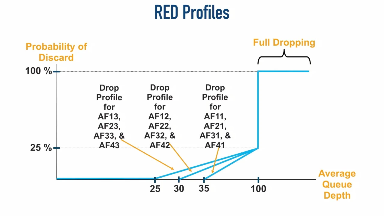
So the second digit gives a queueing algorithm such as Random Early Detection
(RED), used for congestion avoidance, the marking it needs. Whenever there are
more than 25 packets queued, for example, and a 26th comes in, any of the
packets marked with AFx3 (second digit 3) have a certain chance of being
dropped.
On IOS, we can classify (match) VoIP and interactive video traffic in class maps
with match statements, for example match protocol rtp audio, match cos <0-7>, match dscp ef and others. For example:
! Create class map for voice traffic (RTP audio)
class-map match-any VOICE-TRAFFIC
 match protocol rtp audio
 match dscp ef
 match ip precedence 5
 match cos 5

! Create class map for video conferencing traffic
class-map match-any VIDEO-CONF-TRAFFIC
 match protocol rtp video
 match dscp af41 af42 af43
 match ip precedence 4
We mark packets in policy maps:
R1(config)#policy-map DEMO
R1(config-pmap)#class VOICE-TRAFFIC
R1(config-pmap-c)#set ?
  atm-clp        Set ATM CLP bit to 1
  cos            Set IEEE 802.1Q/ISL class of service/user priority
  cos-inner      Set Inner CoS
  discard-class  Discard behavior identifier
  dscp           Set DSCP in IP(v4) and IPv6 packets
  fr-de          Set FR DE bit to 1
  fr-fecn-becn   SET FR FECN-BECN
  ip             Set IP specific values
  mpls           Set MPLS specific values
  precedence     Set precedence in IP(v4) and IPv6 packets
  qos-group      Set QoS Group
  vlan-inner     Set Inner Vlan
Here, we can set cos <0-7>, set dscp <0-63> or with an IETF mnemonic, or
set precedence <0-7> or with a mnemonic.
Congestion Avoidance with Explicit Congestion Notification (ECN)
Now, instead of forcing a TCP Slow Start by dropping packets, it might be better to just ask a sender to slow down. That’s what ECN is all about.
After enabling ECN on Linux (see below), notice that in the initial TCP SYN
segment, the sender will not set the ECN-Capable Transport (ECT) bit of 104
in the IP header. Instead, it will set the Congestion Window Reduced (CWR) and
Explicit Congestion Echo (ECE) flags in the TCP header. If the server supports
ECN, it will send back a TCP SYN+ACK segment with the ECE flag set. Finally,
when the client sends its next segment, completing the TCP 3-way handshake, now
it will set the ECT bit in the IP header (10).
Then, when a router is congested or about to be congested, it can set the
Congestion Experienced (CE) bit to 1 and send the package onwards to its
destination. The recipient will then set the ECE TCP flag in its ACK back to the
sender. The sender notices the ECE bit, reduces its congestion window by half
and sets the CWR flag in its next segment, notifying the receiver that the
traffic flow will slow down a bit.
On Linux, temporarily enable5 with:
# sysctl net.ipv4.tcp_ecn=1
To see it in action, for IPv4, filter with:
# tcpdump 'ip[1] & 0x3 != 0'
For IPv6, filter with:
# tcpdump 'ip6[1] & 0x30 != 0'
Filtering the TCP flags under IPv4 in tcpdump is straightforward:
# tcpdump 'tcp[13] & 0xc0 != 0'
However, this does not show anything when the network protocol is IPv6,
because IPv6 can use extension headers. Those extension headers are indicated in
the IPv6 Next Header field, creating a chain of headers that tcpdump is
currently (version 4.99.5 from April 8 2025) unable to follow. If you know there
are no extension headers involved, ip6[53] & 0xc0 != 0 will address the TCP
flags byte. (40 bytes for the IPv6 header. Unreserved flags are the 14th byte in
the TCP header. And since we are counting from 0: 40 + 14 - 1 = 53.)

We can configure a Cisco router to set the CE bit by configuring WRED with
random-detect ecn from policy-map class config mode (see config example
later). I’m not sure, but it may very well be the case that traffic marked with
ECN, instead of being dropped, always gets the CE bit set when the minimum queue
depth threshold is exceeded. Other, non-ECN traffic is still subject to random
drops.
Prioritizing Traffic using Queuing
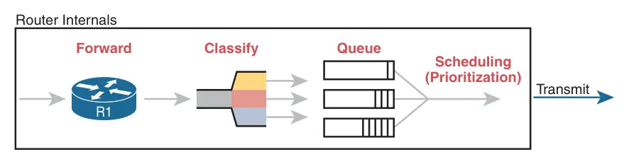
Whenever a router receives traffic faster than it can send it out of a egress queue, the packet gets stored in this queue and has to wait for bandwidth to become available. A queue is a buffer and has finite capacity. We can have multiple queues based on our traffic classes. A queuing algorithm determines what packet to send next from one of the queues.
An old queuing algorithm supported by Cisco is Weighted Fair Queuing (WFQ) where no single flow of traffic can dominate the bandwidth. Notice that this works per-flow, not per-host. A single host with lots of connections can still dominate the bandwidth and starve other hosts that have less flows. WFQ is still recommended for the class-default6: all traffic that is not otherwise classified.
Class-Based Weighted Fair Queuing (CBWFQ) guarantees minimum bandwidth for up to 11 (maximum recommended) classes of traffic. During times of congestion, that minimum bandwidth is guaranteed. If there is no congestion, a class of traffic could use more bandwidth if it needs it. So we could have a queue containing bulk data and guarantee that class 10 or more Mbps.
I’m not completely sure, but according to Cisco documentation, CBWFQ is configured on an interface automatically when a service policy is applied to the interface. See configuration example later on.
A normal queue is created by the bandwidth <kbps> keyword or bandwidth percent <n>
or bandwidth remaining percent <n> in policy-map class config mode.
The queuing algorithm can also handle a single priority queue. This is useful for latency-sensitive applications such as VoIP or video conferencing. Such a Low-Latency Queue (LLQ) gets priority treatment up to a maximum bandwidth during times of congestion. The maximum prevents the LLQ from starving all other queues when the egress is congested. Excess traffic is dropped by a policer.
A priority queue is created by using the priority <kbps> keyword (or the
[remaining] percent <n> alternatives) in policy-map class config mode.
Congestion Avoidance / Drop Management
Queuing is congestion management (what to do in the face of congestion?). Congestion avoidance are strategies to avoid filling queues to capacity to begin with. When a queue is full, it start tail-dropping packets: every new packet that comes in will be dropped. For a protocol like TCP, this will decrease the congestion window: the sender will reduce the amount of traffic it sends before waiting for an acknowledgement (AKA TCP Slow Start). If all TCP flows experience TCP Slow Start at the same time and trigger their congestion control strategy because of tail drop, it is called Global Synchronization. This is an inefficient use of bandwidth.
This is where a congestion-avoidance mechanism such as Weighted Random Early Detection (WRED) comes into play. It starts randomly dropping some packets when the queue depth (amount of packets in a queue) exceeds some defined threshold.
0                 25                 50                 75
|---transmitted---|---some dropped---|xxx all dropped xxx
Let’s say the minimum threshold is 25 packets. Any packets exceeding that number (26th and on), will be subject to random drops. The drops become increasingly likely the deeper the queue becomes. The maximum threshold is 50. Any more packets are not queued, there are unceremoniously dropped.
Randomly dropping some packets triggers the congestion response from some TCP flows (and presumably QUIC flows), so that those flows slow down, while preventing Global Synchronization.
Enable WRED with random-detect in policy-map class configuration mode (see
config example below).
Policing and Shaping
Both policing and shaping have the same goal: to prevent traffic from being sent too rapidly.
Queuing sets a minimum amount of bandwidth we can use; policing and shaping set maximums. Policing drops traffic that exceeds the speed limit we set2; shaping delays traffic by temporarily putting it in a queue.
Both policing and shaping use a “token bucket”. The following formula governs the token bucket:
CIR = Bc / Tc
CIR stands for Committed Information Rate and is the average speed over the interval of a second (the total amount of traffic sent per second).
Bc (Committed Burst) is the number of bits deposited in the token bucket per second divided by the Tc timing interval. If we want to send 64 kbps and the timing interval is 8, the bucket replenishes with 64,000 / 8 = 8,000 bits per timing interval (or 1/8 of a second). The egress still sends at line speed (it has no choice), so it will send those bits out as fast as it can and just be silent the rest of the time.
Configuring QoS on a Cisco Router
Cisco uses something called a Modular QoS CLI (MQC). It consists of 3 steps:
- Create class maps that are used to match the traffic we want to apply QoS to.
- Create one or more policy maps that take the previously defined class maps to apply a mechanism to such as shaping or policing.
- Finally we apply the policy map, usually to a physical interface (but could be an SVI, for example).
Create Class Maps that Match Traffic
R1(config)#class-map match-any EMAIL
R1(config-cmap)#match protocol smtp
R1(config-cmap)#match protocol pop3
R1(config-cmap)#match protocol imap
Here, we create a class map with a made-up name EMAIL (this can be any
string; I make it uppercase so that it stands out from any Cisco keywords). By
default, all the selectors (match statements) must match (logical AND):
change it to logical OR by setting match-any.
Then, in class map config mode, we can use something called Network-Based Application Recognition (NBAR) to match the traffic we want grouped in this map. There are a lot of matching options:
R1(config-cmap)#match ?
  access-group         Access group
  any                  Any packets
  application          Application to match
  class-map            Class map
  cos                  IEEE 802.1Q/ISL class of service/user priority values
  destination-address  Destination address
  discard-class        Discard behavior identifier
  dscp                 Match DSCP in IPv4 and IPv6 packets
  fr-de                Match on Frame-relay DE bit
  fr-dlci              Match on fr-dlci
  input-interface      Select an input interface to match
  ip                   IP specific values
  metadata             Metadata to match
  mpls                 Multi Protocol Label Switching specific values
  not                  Negate this match result
  packet               Layer 3 Packet length
  precedence           Match Precedence in IPv4 and IPv6 packets
  protocol             Protocol
  qos-group            Qos-group
  service              Service Instance to match
  source-address       Source address
  vlan                 VLANs to match
protocol matching might simply look at the destination port of the traffic to
decide whether or not it should be in this class map. Ubiquitous TLS has made
DPI pretty much a no-go these days, I would imagine. Although, match protocol netflix is available, so who knows?
Create Policy Maps that Use Class Maps to Police or Shape Traffic
R1(config)#policy-map DEMO
R1(config-pmap)#class EMAIL
R1(config-pmap-c)#police 256000
Here, we create a policy map with the made-up name DEMO. Again, this can be
any string; I simply made up DEMO and uppercased it to avoid confusion with
Cisco keywords.
Then, we select the class map to apply the policy function to, in our case
EMAIL. We police SMTP, POP3 and IMAP traffic to 256 kbps in times of
congestion. It’s probably a better idea to apply shaping (delaying) and not
policing (dropping) to email traffic, but this is just for the sake of a simple
example.
Here, we could also set WRED with the random-detect keyword and ECN with
random-detect ecn.
Apply Policy Maps to Interfaces
Finally, we apply the policy map to the outgoing side of an interface:
R1(config)#int gig 0/2
R1(config-int)#service-policy output DEMO
All email traffic that leaves interface GigabitEthernet0/2 is now policed to a maximum of 256 kbps in time of congestion.
Note that the CBWFQ queuing algorithm is automatically applied.
Verify Our Work
Show all defined class maps:
R1#show class-map
 Class Map match-any class-default (id 0)
   Match any

 Class Map match-any EMAIL (id 1)
   Match protocol smtp
   Match protocol pop3
   Match protocol imap
Show all defined policy maps:
R1#show policy-map
  Policy Map DEMO
    Class EMAIL
     police cir 256000 bc 8000
       conform-action transmit
       exceed-action drop
Show statistics about how are policy map is applied on an interface:
R1#show policy-map interface gig 0/2
 GigabitEthernet0/2

  Service-policy output: DEMO

    Class-map: EMAIL (match-any)
      0 packets, 0 bytes
      5 minute offered rate 0000 bps, drop rate 0000 bps
      Match: protocol smtp
        0 packets, 0 bytes
        5 minute rate 0 bps
      Match: protocol pop3
        0 packets, 0 bytes
        5 minute rate 0 bps
      Match: protocol imap
        0 packets, 0 bytes
        5 minute rate 0 bps
      police:
          cir 256000 bps, bc 8000 bytes
        conformed 0 packets, 0 bytes; actions:
          transmit
        exceeded 0 packets, 0 bytes; actions:
          drop
        conformed 0000 bps, exceeded 0000 bps

    Class-map: class-default (match-any)
      0 packets, 0 bytes
      5 minute offered rate 0000 bps, drop rate 0000 bps
      Match: any
Books to Read
This post just barely touched the surface of configuring QoS on Cisco devices. The following books came recommended if you really want to get started:
- Enterprise QoS Solution Reference Network Design Guide
- End-to-End QoS Network Design, 2nd edition (Cisco, 2013)
-
This post was inspired by Kevin Wallace’s CCNA videos about QoS and the official CCNA 200-301 study guide by Wendell Odom. The pictures are blatantly stolen from Kevin Wallace’s video and the official study guide; I hope not enough people read this blog for that to matter. Otherwise I have to create my own pictures and I am pressed for time currently because my CCNA exam is soon. You could either buy the videos from Kevin Wallace directly or subscribe to O’Reilly. Highly recommended. ↩︎
-
Or it may just (re)mark the traffic or do nothing and just measure it for later reporting. ↩︎ ↩︎
-
Cisco has a design recommendation to not use over 11 different classes of traffic. ↩︎
-
In reality, the ECN bit pattern of
10and01are treated the same. Both indicate that the sender is capable of doing ECN Transport. To be complete,00means that the sender is not capable, and11means that the sender is capable and a router was congested and set the other bit to1as well. ↩︎ -
On Arch, make permanent by adding to
/etc/sysctl.d/99-sysctl.confand load it withsysctl --system. ↩︎ -
Create a
policy-map <WORD>and thenclass class-defaultand thenfair-queueto enable WFQ for all unclassified traffic. ↩︎