VLANs
VLANs have stumped me for the longest time. They are a requirement for network segmentation, but couldn’t you also achieve that by subnetting? What is the relationship between a VLAN and a subnet? Are they the same thing? In this post, I attempt to answer these and some other questions.
The LAN
A LAN is a layer-2 broadcast segment. That means that layer-2 devices, such as switches, will flood broadcasts, unknown multicasts and multicasts (BUM) out of every interface except the one they received it on. Every NIC on every device on that same segment will have to spend CPU cycles examining the frame to see if it is addressed to that NIC.
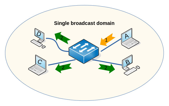
In the diagram, if host A sends a BUM to its LAN (the orange arrow), the switch will forward it out all of its other ports.
To create a second, separate broadcast domain, we need to buy a second switch (and not connect the switches together):
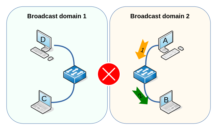
Now, when host A sends traffic onto the link facing the switch, the BUM and unicast traffic will be flooded onto the segment connected with host B. Unsurprisingly, since the two switches are not connected, no traffic coming from host A or B will ever reach host C and D.
We have achieved traffic isolation, but at the price of being potentially very wasteful: if you have a 24-port switch and require 12 devices on 2 different LAN segments, you have to buy 2 switches, even though the single switch has enough ports to spare.
Why Segment Traffic
But let’s back up a little and think about why we might want to segment traffic at all:
- We might want to limit CPU cycles spent by NICs on all BUM traffic.
- We might not want snoopers to have access to all BUM traffic.
- We might want to apply different security policies to different kinds of devices and/or traffic (think network management traffic such as SSH by trusted IT personel versus guest Wi-Fi).
- We might want people in different physical locations be part of the same broadcast domain.
- We might want to keep the STP tree simple and manageable.
Side Note: Why Not Just Route Everything?
When I was building my first networks, I thought, why not just use routing? That is, why not just put every device on its own IP subnet and route all traffic between devices?
- While that definitely works, because routing also gives us traffic isolation, it carries more overhead: a router needs to examine the IP header and change it (TTL, recalculate checksum), whereas a switch looks up the destination address in its CAM table and immediately forwards the frame. Switching, in a word, is faster (wire speed) than routing (10-50+ μs per hop).
- Also, switching requires less or no configuration: you plug the switch in, power it up, attach devices and they can talk, all without setting up (additional) IP subnets.
- Also, routers (and L3 switches) are more expensive and generally have less ports.
Introducing VLANs
VLANs are virtual broadcast domains. They are identified by a 12-bit number (0-4095, although 0 and 4094 and some others are reserved) that groups BUM traffic together. Traffic flowing in different VLANs is completely isolated, as if we had 2 separate, unconnected switches:
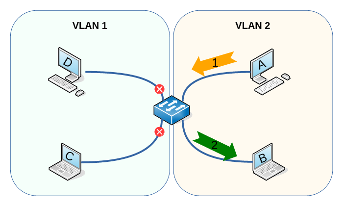
In the diagram, traffic from host A can only ever reach host B or be discarded. VLANs guarantee that no traffic will ever flow from host A or B to host C or D, just as if the switches were physically separated.
To make all traffic coming in on a link part of a VLAN, we can make that port part of the VLAN by assigning it a VLAN ID.
To pass VLAN traffic from switch to switch, we need to somehow tell the other switch which VLAN the traffic belongs to. The easiest approach is to use a Port VLAN ID (PVID or access port) on both sides and use a link per VLAN:
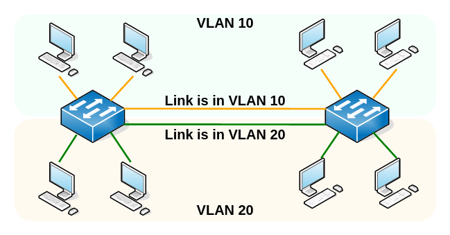
Obviously, that doesn’t scale very well. You would need a separate link for every VLAN. Image having not 2, but 10 or 30 VLANs and soon most of the ports of our switches are unavailable for end devices (the reason we have these switches in the first place).
Enter trunks: we use a single link between switches but we embed the VLAN ID inside the frame:
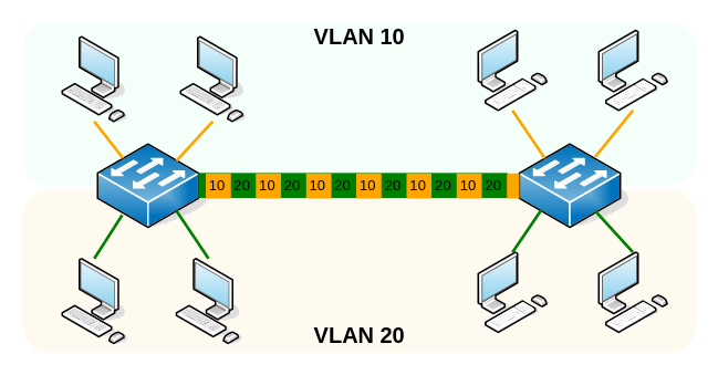
This approach has been standardized in the IEEE 802.1Q standard:
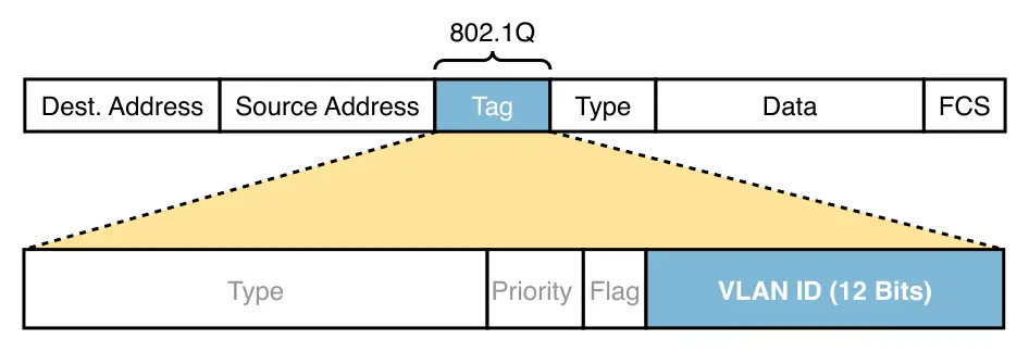
The 802.1Q field is inserted before the EtherType field and has type 0x8100
itself. The receiving switch strips the additional field from the Ethernet
header and forwards it towards its destination.
Routing Traffic between VLANs
Traffic being completely isolated from each other is great, except when you need to talk to a device in another VLAN. To do so, a layer-3 device, such as a router or a layer-3 switch, is needed. Every VLAN typically gets assigned its own subnet, and routers route between these subnets and thus between the VLANs.
One of the most typical topologies for routing between VLANs is the so-called Router-on-a-Stick (ROAS):
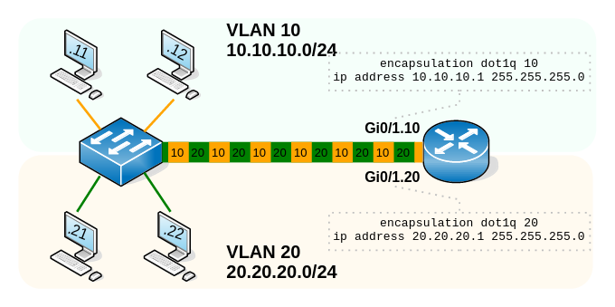
Here, a switch that knows about several VLANs is connected with a single trunk port to a router. The router uses virtual subinterfaces that each know about a separate VLAN. Those subinterfaces are assigned IP addresses in the VLAN subnet. Upon receiving traffic that is part of a specific VLAN, the router decapsulates the Ethernet frame, inspects the IP header, selects the outgoing interface, encapsulates the packet into a new Ethernet frame including an 802.1Q field, and sends it out of the virtual subinterface (over the single physical trunk port) back to the switch.
Configure Cisco
On a Cisco switch, configure an access port as follows:
Switch(config)#int gi 0/1
Switch(config-if)#switchport mode access
Switch(config-if)#switchport access vlan 10
Verify:
Switch#show vlan
To create a trunk port:
Switch(config-if)#switchport encapsulation dot1q
Switch(config-if)#switchport mode trunk
To allow which tags are allowed on the trunk:
Switch(config-if)#switchport trunk allowed vlan 10,20
Verify:
Switch#show interface trunk
Configure MikroTik
Throughput Disclaimer
On MikroTik devices, things are vastly more configurable, more complex and therefore more confusing. First, there is no single configuration that works on all devices. Some switches have specialized hardware (docs here and here) and the configuration reflects that. You can increase throughput by making use of hardware processing instead of using the CPU. While I’ve found the config below to work on a couple of MikroTik devices including a CRS328 L3 switch, I cannot guarantee that it is the best way to do it on all hardware. Read the documentation.
Bridges, Bridge Ports, VLAN interfaces and Tagged and Untagged Egress
With that out of the way, here, I am going to configure a hEX router that
has 5 ports, ether1 through ether5. ether3 and ether4 are going to be
access VLANs, ether5 is going to be a trunk port.
First you create a bridge:
[u@hEX] /interface/bridge/add name=BR
[u@hEX] /interface/bridge/print proplist=name,pvid,vlan-filtering
Flags: D - dynamic; X - disabled, R - running
 0  R name="BR1" pvid=1 vlan-filtering=no
Notice that vlan-filtering says no for the time being to ease configuration.
Add VLAN interfaces:
[u@hEX] /interface/vlan/add name=GUEST_WIFI vlan-id=10 interface=BR
[u@hEX] /interface/vlan/add name=MGMT vlan-id=20 interface=BR
Optionally add IP addresses to those VLAN interfaces so that the MikroTik can be reached on those IPs.
Add ports to the bridge and make ether3 and ether4 access ports by setting
their PVID:
[u@hEX] /interface/bridge/port/add bridge=BR interface=ether3 pvid=10
[u@hEX] /interface/bridge/port/add bridge=BR interface=ether4 pvid=20
[u@hEX] /interface/bridge/port/add bridge=BR interface=ether5
Now for the interesting part: we need to determine at which point during its journey from the physical interface, over the bridge to the VLAN interface an incoming packet should be tagged
I am not completely sure, but it seems to me that a packet should always have a tag on the bridge. How else could the bridge determine to what VLAN interface to send it? Access ports should send traffic untagged on egress, trunk ports should send traffic tagged. And so we end up with the following configuration for access ports 3 and 4:
[u@hEX] /interface/bridge/vlan/add bridge=BR vlan=10 \
\... tagged=BR untagged=ether3
[u@hEX] /interface/bridge/vlan/add bridge=BR vlan=20 \
\... tagged=BR untagged=ether4
Traffic on the trunk port should be tagged both on the bridge and the egress interface:
[u@hEX] /interface/bridge/vlan/add bridge=BR vlan=10,20 \
\... tagged=BR,ether5
Finally, don’t forget to enable PVID behavior and VLAN filtering:
[u@hEX] /interface/bridge/set [find name=BR] vlan-filtering=yes
Configure Linux
Linux is the underlying OS for both Cisco’s IOS XE and MikroTik’s RouterOS so it should surprise no-one that you can configure everything in this article on Linux as well.
However, the one thing I found to be useful, is tagging my Linux traffic with 802.1Q tags. To do that, create a subinterface and configure the tag:
linux# ip link add link eth0 name eth0.10 type vlan id 10
linux# ip address add 10.10.10.2/24 dev eth0.10
linux# ip link set eth0.10 up